There follow sketches of applications expressed in terms of each of the parallel adaptive mesh refinement method, the parallel hp-adaptive method and the parallel many-body problem each built on programming abstractions built on the SDDA.
A distributed and adaptive version of H3expresso 3-D numerical relativity application has been implemented using the the data-management infrastructure presented in this paper. The H3expresso 3-D numerical relativity application is developed at the National Center for Supercomputing Applications (NCSA), University of Illinois at Urbana, has H3expresso (developed at National Center for Supercomputing Applications (NCSA), University of Illinois at Urbana) is a ``concentrated'' version of the full H version 3.3 code that solves the general relativistic Einstein's Equations in a variety of physical scenarios [18]. The original H3expresso code is non-adaptive and is implemented in Fortran 90.
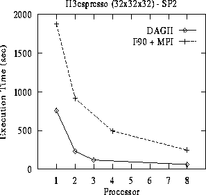
Figure 14: DAGH Overhead Evaluation
The overheads of the proposed DAGH/SDDG representation are evaluated by comparing the performance of a hand-coded, unigrid, Fortran 90+MPI implementation of the H3expresso application with a version built using the data-management infrastructure. The hand-coded implementation was optimized to overlap the computations in the interior of each grid partition with the communications on its boundary by storing the boundary in separate arrays. Figure 14 plots the execution time for the two codes. The DAGH implementation is faster for all number of processors.
The results presented below were obtained for a 3-D base grid of dimension
 and 6 levels of refinement with a refinement factor of
  .
.
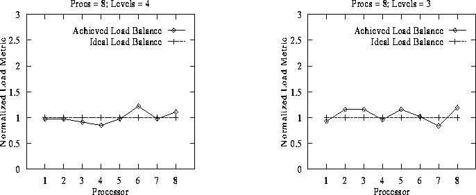
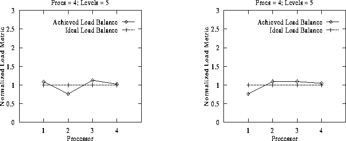
Figure 15: DAGH Distribution: Snap-shot I -
Figure 16: DAGH Distribution: Snap-shot II
Figure 17: DAGH Distribution: Snap-shot III -
Figure 18: DAGH Distribution: Snap-shot IV
To evaluate the load distribution generated by the composite partitioning scheme we consider snap-shots of the distributed grid hierarchy at arbitrary times during integration. Normalized computational load at each processor for the different snap-shots are plotted in Figures 15-18. Normalization is performed by dividing the computational load actually assigned to a processor by the computational load that would have been assigned to the processor to achieve a perfect load-balance. The latter value is computed as the total computational load of the entire DAGH divided by the number of processors.
Any residual load imbalance in the partitions generated can be tuned by varying the granularity of the SDDG/DAGH blocks. Smaller blocks can increase the regriding time but will result in smaller load imbalance. Since AMR methods require re-distribution at regular intervals, it is usually more critical to be able to perform the re-distribution quickly than to optimize each distribution.
Both prolongation and restriction inter-grid operations were performed locally on each processor without any communication or synchronization.
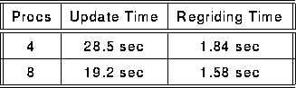
Table 1: Dynamic Partitioning Overhead
Partitioning is performed initially on the base grid, and on the entire grid hierarchy
after every regrid. Regriding any level  comprises of refining at level and all
level finer than ; generating and distributing the new grid hierarchy; and performing
data transfers required to initialize the new hierarchy. Table 1 compares
the total time required for regriding, i.e. for refinement, dynamic re-partitioning and load
balancing, and data-movement, to the time required for grid updates. The values listed are
cumulative times for 8 base grid time-steps with 7 regrid operations.
comprises of refining at level and all
level finer than ; generating and distributing the new grid hierarchy; and performing
data transfers required to initialize the new hierarchy. Table 1 compares
the total time required for regriding, i.e. for refinement, dynamic re-partitioning and load
balancing, and data-movement, to the time required for grid updates. The values listed are
cumulative times for 8 base grid time-steps with 7 regrid operations.
An parallel hp-adaptive finite element code for computational fluid dynamics is in development. This hp-adaptive finite element computational fluid dynamics application has two existing implementations: 1) a sequential FORTRAN code and 2) a parallel FORTRAN code with fully a duplicated data structure. The hp-adaptive finite element data structure has a complexity so great that is was not tractable to distribute the FORTRAN data structure. As such the parallel FORTRAN implementation is not scalable due to the memory consumed on each processor by duplicating the data structure.
To make tractable the development of a fully distributed hp-adaptive finite element data structure is was necessary to achieve a separation of concerns between the complexities of the hp-adaptive finite element data structure and complexities of distributed dynamic data structures in general. This separation of concerns in the development of a fully distributed hp-adaptive finite element data structure provided the initial motivatation for developing the SDDA.
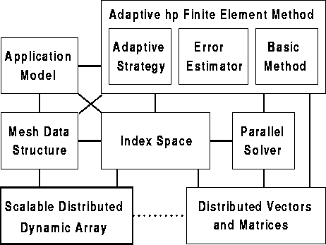
The organization of the new finite element application is illustrated in Figure 19. At the core of the application architecture is the index space. The index space provides a very compact and succinct specification of how to partition the application's problem among processors. This same specification is used to both distribute the mesh structure through the SDDA and to define a compatible distribution for the vectors and matrices formed by the finite element method.
Figure 19: Finite Element Application Architecture
The finite element application uses a second parallel infrastructure which supports distributed vectors and matrices, as denoted in the lower right corner of Figure 19. The development of this infrastructure is also underway in TICAM. The current state of this infrastructure is presented in the Supercomputing'96 paper "Towards Usable and Lean Parallel Linear Algebra Libraries" by Robert van de Geijn, et. al. Both SDDA and linear algebra infrastructures are based upon the common abstraction of an index space. This commonality provides the finite element application with uniform abstraction for specifying data distribution.
Figure 20: Data flow in the fast multipole algorithm
The N-body particle problems arising in various scientific disciplines
appear to require an  computational method.
However, once a threshold in the number of particles is surpassed,
approximating the interaction of particles with interactions between
sufficiently separated particle clusters allows the computational
effort to be substantially reduced.
The best known of these fast
summation approaches is the fast multipole method [19],
which, under certain assumptions, gives a method of
computational method.
However, once a threshold in the number of particles is surpassed,
approximating the interaction of particles with interactions between
sufficiently separated particle clusters allows the computational
effort to be substantially reduced.
The best known of these fast
summation approaches is the fast multipole method [19],
which, under certain assumptions, gives a method of  .
.
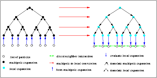
The fast multipole method is a typical divide and conquer algorithm. A cubic computational domain is recursively subdivided into octants. At the finest level the influence of the particles within a cell onto sufficiently separated cells is subsumed into a multipole series expansion. These multipole expansions are combined in the upper levels, until the root of the oct-tree contains a multipole expansion. Then local series expansions of the influence of sufficiently separated multipole expansions on cells are formed. Finally, in a reverse traversal of the oct-tree the contributions of cells are distributed to their children (cf. figure 20). The algorithm relies on a scaling property, which allows cells on the scale of children to be sufficiently separated when they were too close on the scale of the current parents. At the finest level the influence of these sufficiently separated cells is taken into account together with the interaction of the particles in the remaining closeby cells. For a more mathematically oriented description of the shared memory implementation with or without periodic boundary conditions we refer to [21][20] and the references therein.
Figure 20 shows that the fast multipole algorithm is readily decomposed into three principal stages:
A more detailed analysis of the (non-adaptive) algorithm reveals that optimal performance should be attained when each leaf-cell contains an optimal number of particles, thereby balancing the work between the direct calculations and the conversion of the multipole expansions to the local expansions in the second stage.
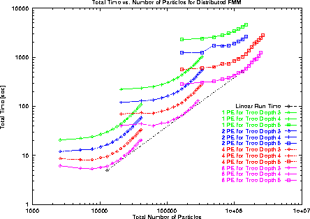
Figure 21: Total Execution Time on SP2 vs. Problem Size for Multiple Levels
of Approximation
Next we describe preliminary performance results for the distributed fast multipole method implemented on the SDDA. We verified the fast multipole method by computing an exact answer for one particle chosen randomly. This comparison was repeated for several small problems until we were certain that the algorithm behaved as expected. Performance measurements were taken from a 16 node IBM SP2 parallel computer running AIX Version 4.1.
The total run times using 3, 4, and 5 levels
of approximation on a variety of problem sizes for 1, 2, 4, and 8 processors
are presented in Figure 21.
We also plot the expected O(  ) run time aligned with the 8 processor
results.
Each curve represents the total execution time for a fixed level of
approximation while increasing the number of particles in the computation.
Two major components of each run time are an approximation time
and a direct calculation for local particles.
The approximation time is a function of the number of levels of
approximation and is fixed for each curve. The direct calculation
time grows as O(
) run time aligned with the 8 processor
results.
Each curve represents the total execution time for a fixed level of
approximation while increasing the number of particles in the computation.
Two major components of each run time are an approximation time
and a direct calculation for local particles.
The approximation time is a function of the number of levels of
approximation and is fixed for each curve. The direct calculation
time grows as O(  ). The problem size for which these two
times are equal represents the optimal number of particles stored
per subdomain.
). The problem size for which these two
times are equal represents the optimal number of particles stored
per subdomain.
The curves for 8 processors align relatively well with the O( ) run time
for all problem sizes. Thus, the algorithm appears scalable for the
problems considered. Furthermore,
these results show that 1 processor has the longest time and 8
processors have the shortest time,
which indicates that some speedup is being attained.
We have presented results for a fast multipole method
which demonstrates the O( ) computational complexity.
These results exhibit both scalability and speedup for a small
number of processors.
Our preliminary results focused on validity and accuracy. The
next step is to performance tune the algorithm.